Install HackerGadgets Battery Board Manual Power Switch
This is a DIY guide for adding a manual power switch to the HackerGadget Battery Board (NVMe version). Raspberry Pi CM5 changed the way power-reset works, thus the power button on the uConsole with long press no longer functions as a hard turning off.
This is particularly useful when kernal panic happens, or software freezes. With the power switch, there is no need to take the back cover off to disconnect the battery, you can simply flip the switch to cut off the power and restart the device.
Warning: This mod involves soldering exterme tiny joints, if you are not experienced with soldering, please seek help from someone who is, or practice on some spare electronics before attempting this mod. Always make sure to disconnect the battery and power source before working on the board to avoid any risk of electric shock or damage to the components.
Materials Needed
- 1 x SMD SPST (Single Pole Single Throw) Toggle Switch (make sure you buy some backups as they are very small and easy to lose or broken during soldering) MSK12C02 is the one I used.
- Wires (can be taken off from JST connector wires as they are heat resistant & easy to solder).
- Printed 3D model for the side extension panel (Purchase & Download the 3D model).
- Soldering iron and solder.
- Heat shrink tubing or electrical tape for insulation.
Step 1: Disassemble the Battery Board
- Remove the battery board from the uConsole by unscrewing the screws and disconnecting the battery connector.
- Don’t forget remove the nvme cable as well, it is connected to the battery board and can be easily damaged during the process.
- Remove the battery from the board to avoid any accidental short circuits while working on the board.
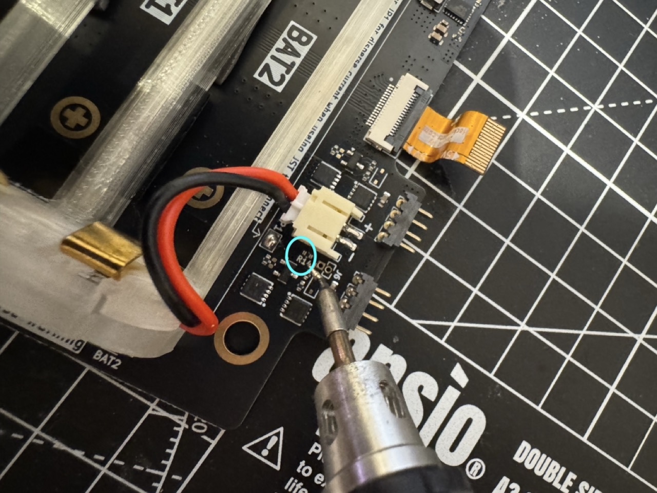
Step 2: Remove the R14 Resistor
Locate the R14 resistor on the battery board. It is a small surface-mount.
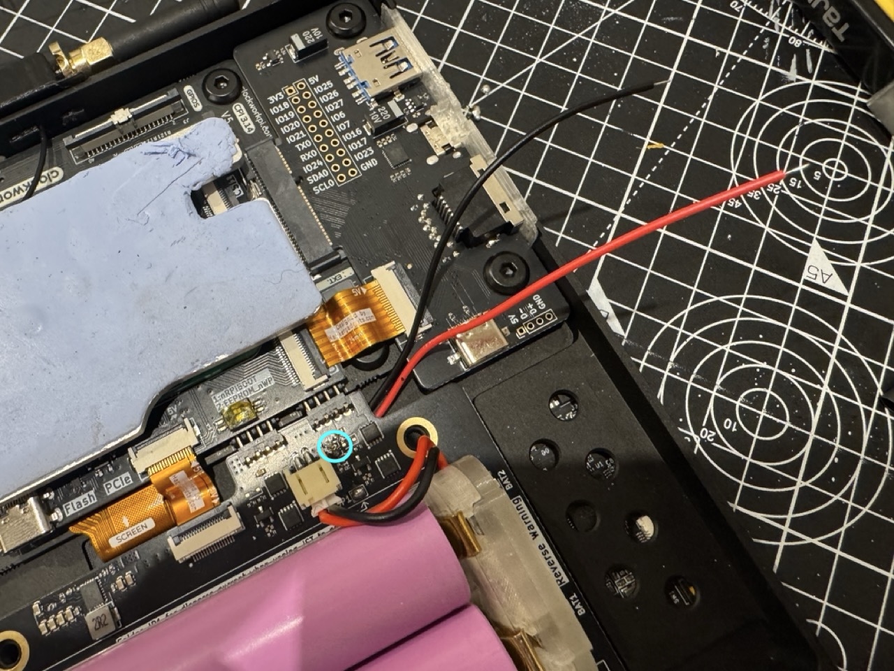
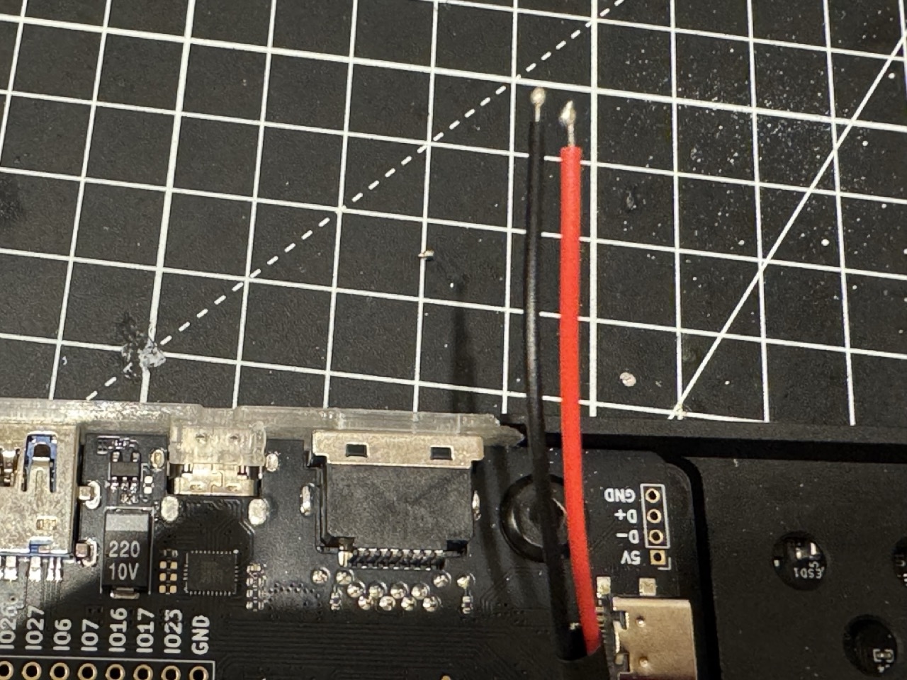
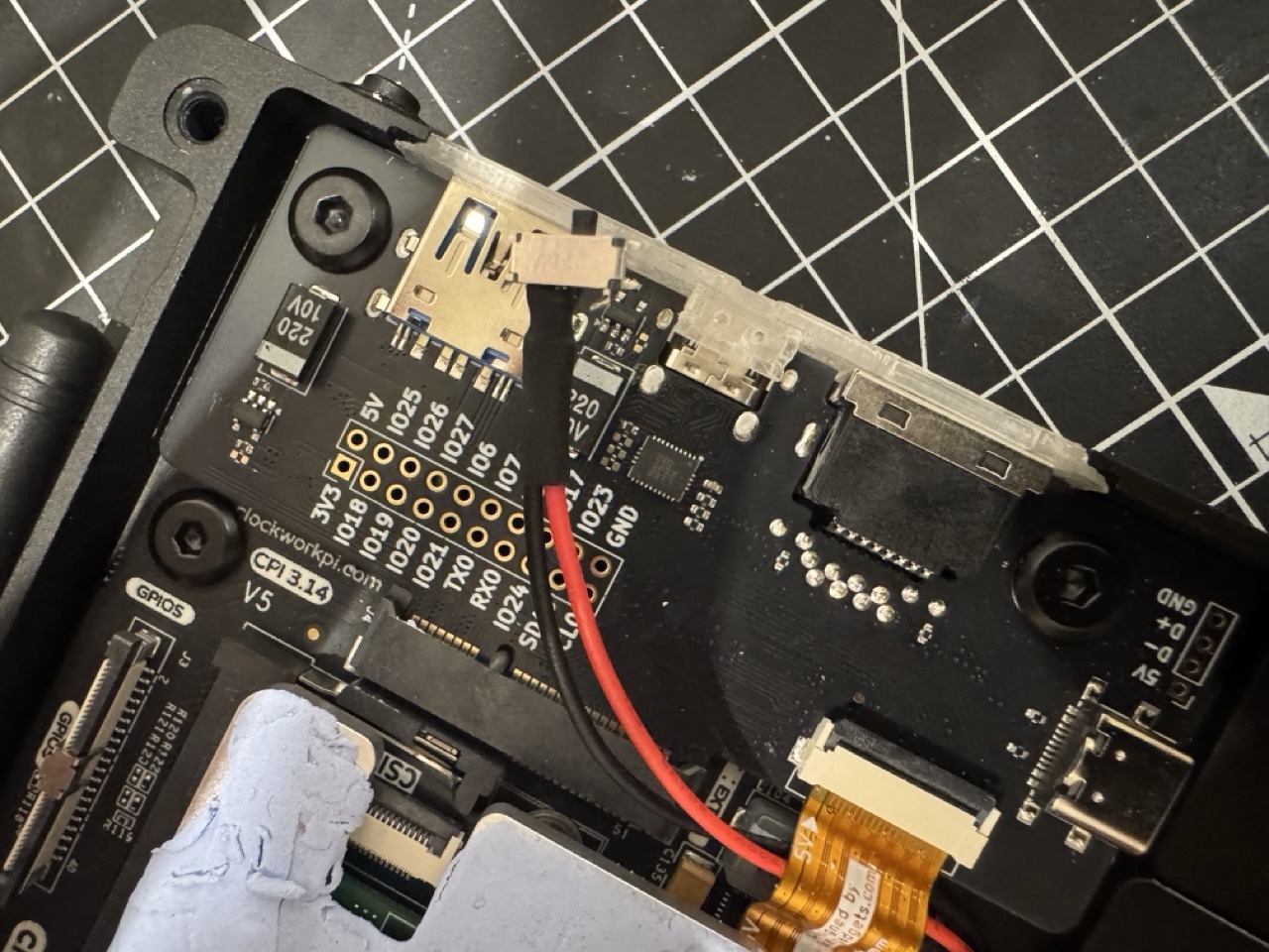
Step 3: Soldering Two Wires to J16
J16 has two spare connectors, since the back has some spaces. It is a cleaner solution to solder the wires from the back and then route it to the front.
Step 4: Tint the Wires & Joints
To make the small joints easier to solder, you can apply a small amount of solder to the wires and the MSK12C02 switch termianls before soldering. They should show a small dot on the tips.
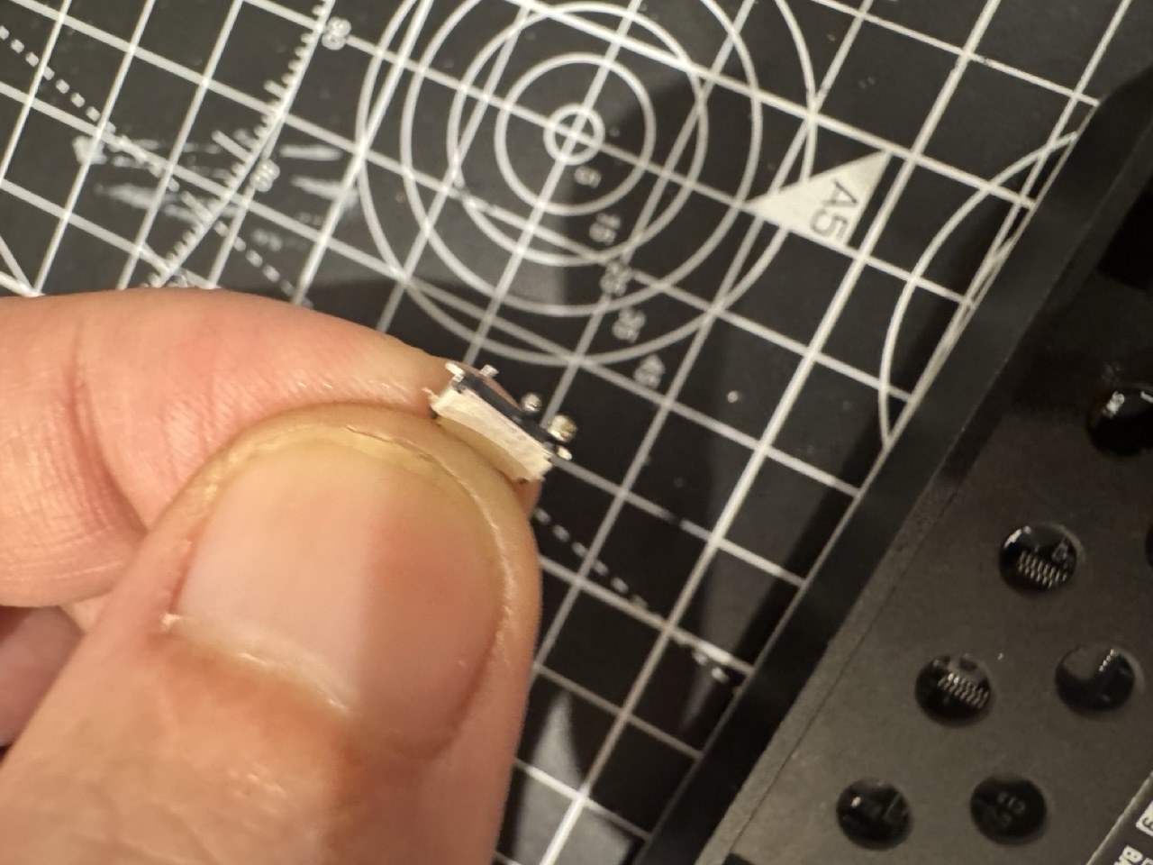
Step 5: Solder the Wires to the Switch
Carefully solder the wires to the terminals of the MSK12C02 switch. In this example, I am using those two pins are closer to each other:
- When switch at top position, the circuit is closed, the battery board is powered on.
- When switch at bottom position, the circuit is open, the battery board is powered off.
Before soldering, place a small strip of heat shrink tube.
This is very small pins, try to use a fine tip & small clamp to hold the switch in place while soldering. Make sure not to use too much solder, as it can create bridges between the pins. Work on one pin at a time, and let the solder cool down before moving to the next pin.
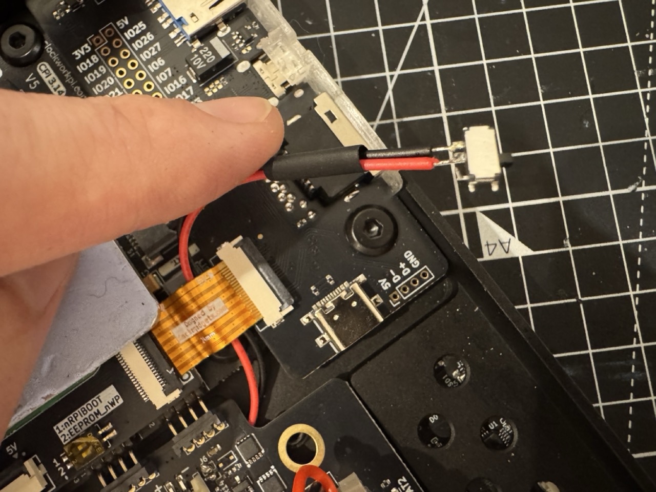
Step 6: Test the Switch
Before reassembling everything, it’s crucial to test the switch to ensure it works correctly. Reconnect the battery board & battery, but do not screw it back in yet. Flip the switch to the “on” position and check if the uConsole powers on, then turn on the uConsole normally. After that, flip the switch to the “off” position and see if the uConsole powers off immediately. If it works as expected, you can proceed to the next step.
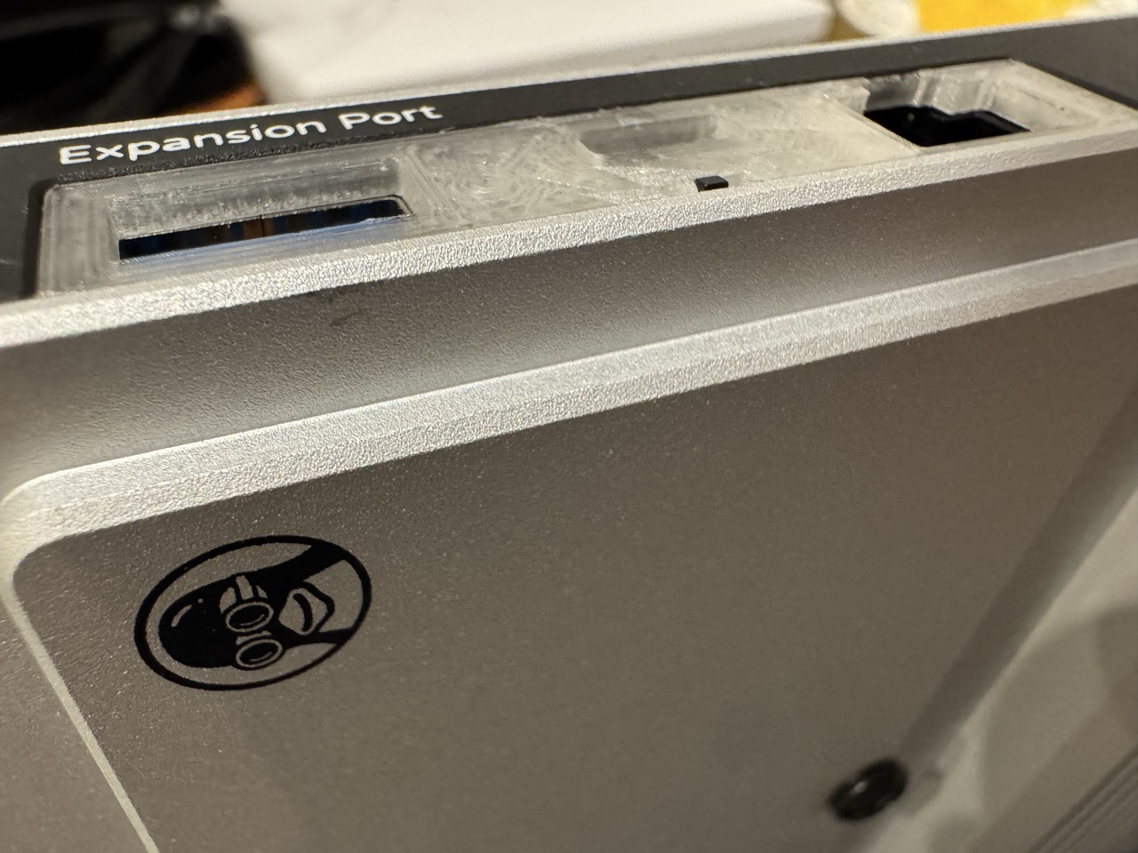
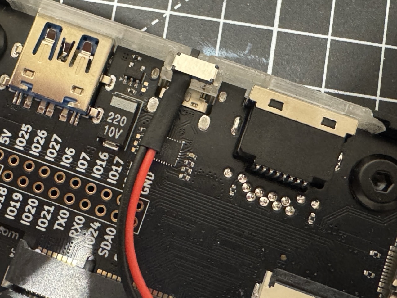
Step 7: Install Switch on the Side Panel
The 3D printed side panel has a slot for the MSK12C02 switch. There is no need for glues or screws, after minor post porcessing cleaning the overhangs, the switch should fit snugly into the slot.
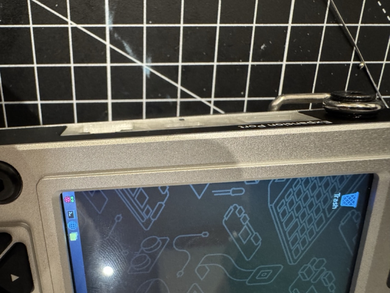
Step 8: Reassemble the uConsole Back Cover
The backcover and the side panel should be able to hold the switch in place without any additional support.
The model was carefully designed, so that it just left enough switch button outside the surface, but not too much to cause accidental switch or obstruction to any connected cables.